
The Bluetooth Low Energy (BLE) protocol, discussed in the previous post, has become a key technology in the Internet of Things (IoT) revolution. BLE differs from its older cousin, Bluetooth Classic, in that it prioritizes low power consumption over high-bandwidth data transmission. This makes it a perfect choice for functions like command and control of networked devices in an IoT ecosystem. The protocol is presently found in use cases as diverse as one-way beacons, tracking tags, and wearable heart monitors.
Despite its prevalence in our daily lives, it can be rather difficult to get a sense of what these BLE communications actually look like. As of writing this article, standard packet sniffing programs like Wireshark do not include native support for this relatively new protocol. Specialized hardware and software solutions are required to capture these frames in transmission and parse their fields to make sense of the raw “bytes on the wire”. Before jumping into the technical approach for doing so, it is helpful to understand a bit more about the anatomy of the BLE protocol.
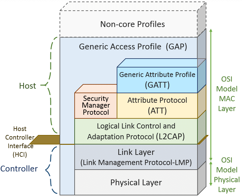
The stack is built on a Physical Layer and Link Layer that will sound familiar to readers who know their Open Systems Interconnect (OSI) model. In Bluetooth 5.0 and earlier, the data transmission rate supported by physical layer standards was fixed at 1 Mbps (data throughput higher up in the stack would necessarily be less due the overhead of header fields in each layer). However starting with Bluetooth 5.1, the BLE protocol now supports a high bandwidth option with 2 Mbps speeds and a “long range” option of 500 or 125 Kbps that sacrifices bandwidth for range.
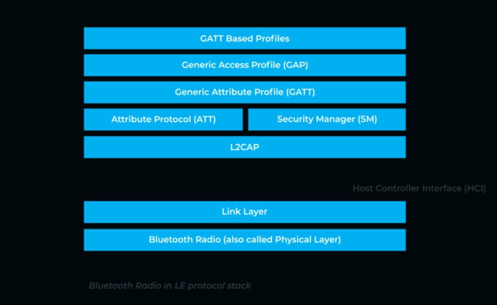
Further up in the stack things start to get interesting The Logical Link Control and Adaptation Protocol (L2CAP) provides multiplexing and segmentation services to higher level protocols. In short, it breaks up application data from higher level protocols into standard BLE packets that can be processed by lower layers in the stack. Together with the BLE Link Layer, it provides roughly the equivalent of the Data Link Layer found in traditional 802.11 and Ethernet networks. In between the L2CAP and Link Layer sits the Host Controller Interface (HCI) which passes commands between the ‘host’ and ‘controller’ portions (see Figure 1) of the protocol stack.
The Security Manager Protocol (SMP) carries out the essential function of managing encryption keys and executing key exchanges to protect user data. The Generic Attribute Profile (GATT) and Attribute Protocol (ATT) are how the applications seeking to use the Bluetooth interface actually communicate with one another. A connected device can either be a ‘GATT server’ that serves up data or a ‘GATT client’ that accesses it. The ATT dictates exactly how these pieces of data will be exposed to another device.
At the top of the stack is the Generic Access Profile (GAP) which controls the connection-related functionality by dictating how Bluetooth devices interact with each other. It specifies three device aspects that govern this behavior: roles, modes, and aspects. A device can have a role of broadcaster that sends one-way packet transmission (like a beacon) or observer that passively listens for such traffic (like an adtech client). A device can also have a role as peripheral or central depending on whether it initiates or completes a connection. Different modes for discoverability and connectivity govern how a device can be found and whether it can establish a connection with other devices. Finally, procedures specify steps for a device to reach a goal such as establishing a paired connection.

Above is a packet capture (PCAP) depicting BLE traffic (more on how to get to this product in the next post). The BLE Link Layer is clearly visible just below the Physical layer frame data and a metadata header added by the BLE sniffer software. As this is an advertising frame, it is rather light on ‘application layer’ data, but it is enough to help get a visual sense of what these BLE packets look like in the wild. In the next post we will explore the hardware components necessary to sniff BLE traffic and generate your own PCAPs!
Cover image source: Novel Bits.

One response to “The Anatomy of a BLE Packet”
Great start.
LikeLike